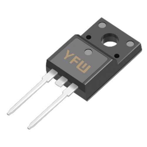
Characteristics, Working Principle, and Key Parameters of Unidirectional Thyristors (SCRs)
Date:2025-06-19 Categories:Product knowledge Hits:806 From:Guangdong Youfeng Microelectronics Co., Ltd
Unidirectional Current Flow
SCRs conduct current exclusively from the anode to the cathode, blocking reverse current when the cathode voltage exceeds the anode voltage. This property makes them ideal for rectification tasks, such as converting alternating current (AC) to direct current (DC) in battery chargers and power supplies, where unidirectional energy transfer is required.
Latch-Up Behavior
A defining feature of SCRs is their ability to "latch" into conduction once triggered. A small gate signal initiates conduction, and the device remains on until the anode current drops below the holding current (Iₕ) or the voltage polarity reverses. This eliminates the need for continuous gate power, reducing control circuit complexity in high-power systems like motor drives and inverters.
Robust Four-Layer Structure
Comprising three PN junctions (J1: P-N, J2: N-P, J3: P-N) in a PNPN configuration, SCRs feature a rugged design capable of withstanding high voltages (up to 6,000V) and currents (up to 5,000A in industrial models). This structure ensures reliability in harsh environments with voltage spikes or surge currents.
Low-Frequency Operation
SCRs have a relatively slow switching speed, typically limited to frequencies below 400Hz, due to their inherent turn-off delay. While this restricts their use in high-frequency applications, it positions them as optimal choices for low-frequency, high-power scenarios where MOSFETs or IGBTs may lack the necessary current-handling capacity.
SCRs operate in three distinct states based on terminal voltages and gate activation:
Voltage Condition: Anode positive relative to cathode (Vₐ > Vₖ), gate untriggered (V₉ = 0V).
Junction Behavior: Junctions J1 and J3 are forward-biased, but J2 is reverse-biased, creating a high-resistance path that blocks significant anode current (Iₐ ≈ 0A). The device remains in this state until the gate receives a trigger signal.
Activation: A positive gate voltage (V₉ ≥ V₉ₜ) or current (I₉ ≥ I₉ₜ) injects carriers into the N-layer near J2, initiating a regenerative process.
Conduction Mechanism: The amplified current through J2 lowers the device’s resistance, causing a rapid transition to a low-voltage drop state (Vₐₖ ≈ 1V). Once conducting, the SCR maintains this state without continuous gate power—a result of its latching behavior.
Voltage Condition: Cathode voltage exceeds anode voltage (Vₖ > Vₐ), reverse-biasing all three junctions.
Current Flow: The device blocks reverse current, similar to a diode in reverse bias, ensuring safety in circuits with alternating voltage polarities.
To turn off an SCR, the anode current must drop below Iₕ (natural commutation in AC circuits) or the voltage must be actively reversed (forced commutation in DC circuits), a critical consideration for circuit design.
Voltage Ratings
Forward Blocking Voltage (Vᴰᴿᴹ): The maximum repetitive forward voltage the SCR can block in the off state without triggering (e.g., 600V, 1200V).
Reverse Blocking Voltage (Vᴿᴿᴹ): The maximum repetitive reverse voltage the device can withstand without breakdown, ensuring reliability in AC applications.
Current Ratings
Average On-State Current (Iₜ(ₐᵥ)): The maximum average current the SCR can carry continuously under specified thermal conditions (e.g., 10A, 200A). Derating is necessary for inductive loads or high-temperature environments to prevent overheating.
Holding Current (Iₕ): The minimum anode current required to maintain conduction. If Iₐ < Iₕ, the SCR reverts to the blocking state, critical for designing commutation circuits in AC systems.
Gate Trigger Parameters
Trigger Current (I₉ₜ): The minimum gate current needed to initiate conduction at a specified anode-cathode voltage (e.g., 5mA–50mA).
Trigger Voltage (V₉ₜ): The corresponding gate voltage (typically 0.8V–3V). Low trigger requirements simplify gate drive design and reduce control circuit power consumption.
On-State Voltage Drop (Vₜ)
The voltage drop across the SCR when fully conducting (1.2V–1.5V for most models), directly impacting power loss (P = Vₜ × Iₐ) and necessitating appropriate heat sink design to manage thermal dissipation.
Turn-Off Time (tᵩ)
The time required for the SCR to regain blocking capability after reverse commutation, limiting its maximum operating frequency and influencing suitability for specific applications.
SCRs are pivotal in low-frequency, high-power scenarios:
Rectification Systems: Converting AC to DC in industrial power supplies and battery chargers, leveraging their unidirectional conduction.
Motor Control: Regulating speed in DC motors by adjusting the conduction angle of the input voltage, enabling efficient power control.
Renewable Energy: Managing power flow in solar inverters and wind turbine converters, where they handle surge currents during grid synchronization.
Designers must prioritize matching SCR parameters to application requirements, ensuring adequate heat sinking, robust gate drive circuits, and protection against voltage transients to prevent misfiring or catastrophic failure.
Unidirectional thyristors (SCRs) are indispensable in power electronics due to their unique combination of high-power handling, latching efficiency, and simple control requirements. While their switching speed limits high-frequency use, their reliability in rectification, motor drives, and energy conversion remains unmatched. By understanding their characteristics, working principle, and key parameters, engineers can harness SCRs to create efficient, durable circuits that underpin modern industrial and sustainable energy systems, proving that classic semiconductor technology continues to drive innovation

Previous:
Classification, Structure, and Principle of MOSFET
Next:
Identification of Common Electronic Components