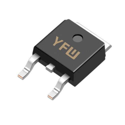
Identification of Common Electronic Components
Date:2025-06-19 Categories:Product knowledge Hits:850 From:Guangdong Youfeng Microelectronics Co., Ltd
Resistors regulate current flow and are identified by physical markings or package types:
Through-Hole Resistors:
Axial-lead resistors use 4–5 color bands:
First 2–3 Bands: Significant digits (e.g., black=0, brown=1, red=2).
Multiplier Band: Power of 10 (gold=×0.1, silver=×0.01, green=×10⁵).
Tolerance Band: Accuracy (e.g., gold=±5%, silver=±10%, no band=±20%).
Example: Yellow-Violet-Red-Gold = 47×100Ω ±5% = 4.7kΩ ±5%.
Surface-Mount Resistors (SMD):
Marked with 3–4-digit codes: "100" = 10Ω, "103" = 10kΩ, "0R5" = 0.5Ω. Tiny 0402/0603 packages may lack markings—refer to PCB silkscreen (e.g., "R12" for a 1206 resistor).
Circuit Symbol: A zigzag line (ANSI) or rectangle (IEEE), labeled "R" (e.g., R₅ = 100kΩ).
Capacitors differ by type and polarization:
Ceramic Capacitors (Non-Polarized):
Disc or rectangular SMD components with 3-digit codes: "104" = 10×10⁴pF = 100nF. Tolerance codes (J=±5%, K=±10%) follow values.
Electrolytic Capacitors (Polarized):
Cylindrical through-hole parts have "+" (anode) and "-" (cathode) marks; the cathode lead is shorter or has a striped casing. SMD tantalum capacitors feature a "+" on the body and direct labeling (e.g., "10µF 25V").
Film Capacitors (Non-Polarized):
Metallized polypropylene/ polyester types (e.g., MKT, CBB) are oval or box-shaped, marked with values like "223J 100V" (22nF, ±5%, 100V).
Circuit Symbol: Two parallel lines (non-polarized) or one curved line (polarized cathode), labeled "C" (e.g., C₃ = 470µF/35V).
Inductors are identified by their core material and winding structure:
Through-Hole Inductors:
Coiled around ferrite/iron cores (axial leads) or air cores (radial leads). Markings include color bands (similar to resistors, e.g., "brown-black-red" = 1000µH) or direct values: "100nH ±20%".
SMD Inductors:
Flat, shielded components with numerical codes: "47N" = 47nH, "10M" = 10µH (M=±20% tolerance). Power inductors have larger footprints (e.g., 1210, 1812) for high-current applications.
Circuit Symbol: Series of loops (air core) or loops with a solid line (ferrite core), labeled "L" (e.g., L₂ = 1mH).
Diodes feature a cathode band and vary by function:
Rectifier Diodes (e.g., 1N4001):
Cylindrical with a black cathode band, rated by peak reverse voltage (50V–1000V) and current (0.5A–3A).
Zener Diodes (e.g., 1N4733A):
Similar in shape to rectifier diodes but marked with voltage ratings: "1N4733A" = 5.1V Zener. The cathode band indicates the breakdown voltage side.
Light-Emitting Diodes (LEDs):
Through-hole LEDs have a longer anode lead and a flat side on the cathode. SMD LEDs (0603, 1206) use package codes; color (red, green, blue) corresponds to emission wavelength.
Circuit Symbol: A triangle pointing to a vertical line (cathode), labeled "D" (e.g., D₇ = 1N5819 Schottky diode).
Transistors are classified into BJTs and MOSFETs, distinguished by pinouts and packages:
Bipolar Junction Transistors (BJTs):
NPN (e.g., 2N2222) and PNP (e.g., 2N3906) types in TO-92 (small signal) or TO-220 (power) cases. Facing the flat side, pins are Emitter (E), Base (B), Collector (C) for NPN; PNP follows the same layout with reversed current flow.
Metal-Oxide-Semiconductor FETs (MOSFETs):
SOT-23 (small signal) or TO-247 (power) packages. Markings like "IRF540" (N-channel, 100V, 33A) indicate type and ratings. Gate (G) is the central pin; Drain (D) and Source (S) require datasheet confirmation for pinout.
Circuit Symbol: BJT has an emitter arrow (NPN: out, PNP: in); MOSFET features a broken line (enhancement mode) with Gate floating, labeled "Q" (e.g., Q₁ = 2SK2698 MOSFET).
ICs are identified by package type and part numbers:
Dual In-Line Package (DIP):
Rectangular with two pin rows. Pin 1 is marked with a dot/notch; numbering is counterclockwise (e.g., "LM7805" 3-pin voltage regulator, "NE555" 8-pin timer).
Surface-Mount Packages:
SOP (Small Outline Package): Gull-wing pins, marked with part numbers (e.g., "TL082" dual op-amp, "CD4011" quad NAND gate).
QFP (Quad Flat Pack): Four-sided pins for microcontrollers (e.g., "STM32F103" with 48–144 pins).
BGA (Ball Grid Array): Solder balls under the package, used in high-density chips (e.g., "APM8950" application processor).
Circuit Symbol: A rectangle with pin numbers, denoted by "U" (e.g., U₄ = "74LS04" hex inverter).
Multimeter Verification: Use diode test mode for diodes/transistors, capacitance/inductance modes for passive components when markings are ambiguous.
Datasheet Reference: Critical for SMD components (e.g., 0201 resistors without markings) or complex IC pinouts—always cross-check with manufacturer specs.
Polarity Caution: Ensure correct orientation for polarized components (electrolytic capacitors, diodes, MOSFETs) to avoid damage from reverse voltage.
Accurate identification of electronic components is vital for reliable circuit performance. Each component—from color-coded resistors to multi-pin ICs—carries distinct physical and symbolic markers that guide its use. By mastering these identifiers and leveraging datasheets, engineers can ensure proper selection and installation, driving optimal system functionality. Trust in high-quality components from suppliers like YFW (
https://www.yfwdiode.com/) enhances project reliability, making component identification a cornerstone of successful electronic design

Previous:
Classification, Structure, and Principle of MOSFET
Next:
The Role of Thyristors in Electrical Circuits