Resistors are passive components that control current flow. When damaged, they often exhibit subtle yet critical signs:
Open Circuit: A burnt or cracked resistor body indicates thermal overload . Testing with a multimeter in resistance mode will show "OL" (open loop), meaning the resistor has failed to conduct .
Value Drift: Resistors may lose their nominal value due to prolonged heat exposure. For example, a 1kΩ resistor might measure 1.2kΩ, causing voltage divider inaccuracies.
Physical Damage: Discoloration or charring suggests excessive current. Replace immediately to prevent cascading failures.
Detection Tips: Always disconnect the resistor from the circuit before testing. Use a digital multimeter to compare measured values against the color code or label. YFW’s precision resistors are designed with high-temperature tolerance to minimize drift .
Capacitors store and release energy, but their electrolyte-based design makes them vulnerable to aging:
Bulging or Leaking: Aluminum electrolytic capacitors often bulge at the top or leak brown fluid when degraded. This reduces capacitance and causes ripple voltage in power supplies .
Short Circuit: A capacitor stuck in a discharged state will fail to charge, leading to unstable voltage outputs. A multimeter’s capacitance mode will show zero or negative values.
ESR Increase: High Equivalent Series Resistance (ESR) causes overheating and poor filtering. Specialized ESR meters are ideal for accurate diagnosis.
Prevention: Avoid reverse voltage application and ensure operating temperatures stay within specifications. YFW’s low-ESR capacitors are engineered for longevity in high-frequency applications .
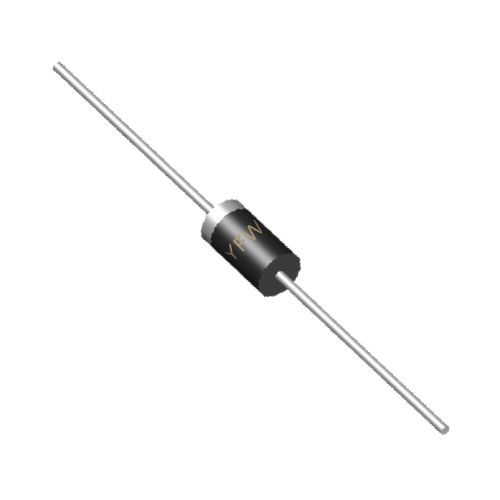
Diodes allow current flow in one direction. Failure modes include:
Open Circuit: A diode that no longer conducts in forward bias (tested with a multimeter’s diode mode showing "OL") is open. This disrupts rectification in power supplies .
Short Circuit: A diode conducting in both directions (measured voltage <0.3V in reverse bias) indicates a short. This can cause excessive current and Burn it down adjacent components .
Overheating: A hot diode suggests current overload. Check for soldering defects or mismatched specifications.
YFW Solution: Our 1N5408 rectifier diodes feature 3A current handling and 1kV reverse voltage, ensuring robust performance in rectification circuits .
Transistors amplify signals or act as switches. Common failure symptoms include:
Gain Loss: A transistor with reduced β (current gain) will distort output signals. Use a transistor tester to verify hFE values .
Collector-Emitter Short: A short circuit between collector and emitter (measured resistance near 0Ω) results in uncontrolled current flow.
Thermal Runaway: Overheating due to inadequate heat sinking causes gradual performance degradation.
Testing Steps: For BJT transistors, test base-emitter and base-collector diodes using a multimeter. A PNP transistor should show forward voltage drops between 0.6-0.8V for silicon types . YFW’s SR560 Schottky diodes offer low forward voltage (0.7V) to minimize power loss .
ICs are complex, and their failures often manifest as:
No Output Signal: A non-responsive IC may be due to a blown fuse, cracked solder joints, or electrostatic discharge (ESD) damage.
Overheating: A hot IC indicates internal short circuits or excessive load. Check for voltage spikes in the power rail.
Intermittent Operation: Corrosion on pins or loose connections cause erratic behavior. Inspect for greenish deposits (copper oxide) .
Diagnosis: Use an oscilloscope to trace signals through the IC. Replace suspect ICs with identical models, ensuring proper socket alignment. YFW’s automotive-grade ICs undergo rigorous ESD testing for reliable performance .
Corrosion: Humidity and contaminants cause metallic contacts to oxidize, increasing resistance. Regular cleaning with isopropyl alcohol and conformal coating can mitigate this .
Mechanical Stress: Bent leads or cracked packages from physical impact weaken structural integrity. Handle components with care during soldering.
Identifying damaged components requires a combination of visual inspection, multimeter testing, and circuit analysis. YFW’s commitment to quality ensures our resistors, diodes, and transistors meet stringent reliability standards, minimizing downtime and repair costs. For critical applications, consider Preventive maintenance strategies like thermal imaging and periodic component checks. Visit
www.yfwdiode.com to explore our full range of high-performance electronic components.
YFW – Powering Innovation with Precision Engineering