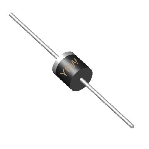
A thyristor is a four-layer (PNPN), three-terminal device with an anode (A), cathode (K), and gate (G) . Its structure resembles two interconnected bipolar junction transistors (BJTs)—a PNP and an NPN—sharing a common base-emitter junction. This configuration creates a regenerative feedback loop, enabling the device to switch between forward blocking and forward conduction states.
In its default state, the thyristor remains in forward blocking mode when the anode is positively biased relative to the cathode but no gate signal is applied. During this phase, the middle PN junction (J2) acts as a reverse-biased barrier, preventing current flow . To transition into forward conduction mode, specific conditions must be met.
The first prerequisite for thyristor conduction is a positive voltage across the anode and cathode (Uₐₖ > 0). This forward bias aligns the PN junctions J1 and J3 in the forward direction, while J2 remains reverse-biased. However, a forward voltage alone is insufficient to trigger conduction without additional activation .
The most common method to initiate conduction is through gate triggering. A positive voltage pulse applied to the gate terminal (relative to the cathode) injects minority carriers into the P-layer, reducing the depletion width at J2. This action lowers the forward breakover voltage (V_BO), allowing the device to transition into conduction .
Minimum Trigger Current (I_G(min)): The gate current must exceed a critical threshold to ensure reliable triggering. This value varies by device but is typically in the milliampere range.
Pulse Duration: The gate pulse must be sufficiently long to ensure the thyristor enters latching mode, where internal feedback sustains conduction even after the pulse is removed .
Once triggered, the thyristor enters latching mode, requiring a minimum latching current (I_L) to maintain conduction. This current is higher than the subsequent holding current (I_H) needed to sustain operation . If the anode current drops below I_L during triggering, the device may fail to latch and revert to blocking mode.
After latching, the thyristor remains conductive as long as the anode current exceeds the holding current (I_H). I_H is the minimum current required to maintain the regenerative feedback loop. If the current falls below I_H—due to reduced voltage or external circuit changes—the device turns off and returns to forward blocking mode .
This is the most reliable and widely used method. YFW’s thyristors are designed with precise gate characteristics to ensure consistent triggering at low power levels. For example, a resistor (R₁) in the gate circuit limits current to prevent damage, while a gate-cathode resistor (R_GK) suppresses spurious triggering from noise or thermal effects .
In this method, the forward anode-cathode voltage exceeds the forward breakover voltage (V_BO), causing avalanche breakdown at J2. However, this approach is risky, as V_BO is typically higher than the device’s rated voltage, potentially leading to failure . YFW’s products are engineered to operate safely within specified voltage limits, minimizing the need for this method.
While less common, thyristors can also be triggered by temperature changes (e.g., thermal runaway) or light exposure (used in specialized opto-coupled applications). These methods are niche and require careful design to avoid unintended activation .
YFW’s thyristors are integrated into various high-power systems, including:
AC Motor Control: By regulating the firing angle of thyristors in AC circuits, engineers can adjust motor speed and torque efficiently .
Power Converters: Thyristors enable rectification and inversion of AC/DC power, critical for renewable energy systems and industrial machinery.
Overvoltage Protection: Crowbar circuits using thyristors safeguard equipment by short-circuiting during voltage spikes .
While thyristors are semi-controlled devices (they cannot be turned off via the gate), they can be deactivated by:
Natural Commutation: Reducing the anode current below I_H during zero-crossing in AC circuits.
Forced Commutation: Using external circuits (e.g., capacitors or auxiliary thyristors) to reverse-bias the device and interrupt current flow .
Understanding the conduction conditions of thyristors is essential for designing robust power electronics systems. YFW Microelectronics’ thyristors adhere to rigorous standards, ensuring reliable performance across diverse applications. By combining forward anode voltage, precise gate triggering, and optimal current management, these devices deliver efficient control and durability. For more information on YFW’s semiconductor solutions, visit
www.yfwdiode.com.
YFW Microelectronics – Powering Innovation in Semiconductor Technology.
