A thyristor is a four-layer (PNPN) semiconductor device with three terminals: Anode (A), Cathode (K), and Gate (G). Its operation is based on the interaction of two interconnected transistors (a PNP and an NPN) forming a regenerative feedback loop .
The PNPN structure creates three PN junctions (J1, J2, J3). When a positive voltage is applied between the anode and cathode (VAK > 0), junction J2 becomes reverse-biased, blocking current flow. However, a small trigger current at the gate (IG) causes the device to transition from the forward-blocking state to the conducting state .
Triggering Mechanism:
Applying a positive pulse to the gate injects minority carriers into the N layer, reducing the reverse bias at J2. This initiates a chain reaction where the PNP and NPN transistors saturate, allowing current to flow from the anode to the cathode. Once triggered, the thyristor remains even after removing the gate signal, as long as the anode-cathode current (IT) exceeds the holding current (IH) .
Turn-Off Conditions:
The thyristor turns off only when the anode current drops below IH or the anode-cathode voltage reverses (e.g., in AC circuits). This makes thyristors suitable for switching applications but requires careful design for proper commutation .
Holding Current (IH): The minimum current required to maintain conduction.
Latching Current (IL): The minimum current needed to keep the thyristor on after triggering.
Gate Trigger Voltage (VGT) and Current (IGT): The threshold values for triggering the gate .
Unidirectional SCR: Conducts current only in one direction (anode to cathode), used in rectification and DC motor control .
Bidirectional TRIAC: Functions as two SCRs in reverse parallel, allowing bidirectional current flow. Ideal for AC applications like 调光 and motor speed control .
Proper wiring is critical to ensure thyristor functionality and safety. Below are common wiring scenarios for SCRs and TRIACs.
A typical SCR circuit includes the main power loop (anode-cathode) and the gate control circuit.
TRIACs are used in AC circuits and require a different approach due to bidirectional conduction.
Components:
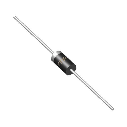
TRIAC (e.g., YFW’s BT131-800 for 1A RMS current ).
AC power source.
Trigger circuit (diac, resistor, and capacitor for phase control).
Wiring Steps:
Connect the TRIAC’s main terminals (MT1 and MT2) in series with the load.
Connect the gate to a diac-triggered circuit. The diac ensures triggering in both halves of the AC cycle .
Example Circuit:
In a light dimmer, the TRIAC’s gate is triggered by a variable resistor-capacitor network. Adjusting the resistor changes the phase angle of the trigger pulse, controlling the lamp’s brightness .
Heat Dissipation: Thyristors generate heat during conduction. Use heat sinks for high-power applications (e.g., YFW’s SOT-223 proper thermal management).
Overvoltage Protection: Include RC snubber circuits to suppress voltage transients .
Gate Protection: Limit gate current to prevent damage. For YFW’s BT131-800, ensure IGT ≤ 10mA .
Thyristors are versatile and find use in various industries:
Power Control: AC voltage regulation in heaters and lighting .
Motor Control: Speed adjustment for fans and pumps using TRIACs .
Industrial Automation: High-power switching in manufacturing equipment .
Renewable Energy: Inverters for solar and wind systems .
YFW’s thyristors, such as the BT131-800, are engineered for robustness in these applications, offering high voltage ratings (800V) and low gate trigger currents .
Failure to Trigger: Check gate voltage, current, and polarity. Ensure VGT and IGT thresholds are met .
Premature Turn-Off: Verify anode current exceeds IH. In AC circuits, ensure the load current does not drop below IH before the voltage zero-crossing .
Overheating: Check heat sink installation and current ratings. Use YFW’s datasheets for thermal derating guidelines .
Thyristors are essential for high-power control due to their ability to switch large currents with minimal gate power. Understanding their working principle and proper wiring ensures optimal performance and reliability. YFW’s thyristors, designed with precision and durability, are ideal for diverse applications, from household appliances to industrial systems. For detailed technical specifications and application notes, visit
www.yfwdiode.com.
For more insights, explore YFW’s range of thyristors and technical resources