An SCR is a four-layer, three-terminal semiconductor device that acts as a switch. Its structure consists of alternating P-type and N-type materials, forming three PN junctions. The three terminals are:
Anode (A): The main current-carrying terminal connected to the positive side of the power supply.
Cathode (K): The terminal connected to the negative side of the power supply or load.
Gate (G): The control terminal that triggers the SCR into conduction when a small current is applied.
Most SCRs feature clear markings on their packaging to indicate terminal positions. Here’s how to identify them:
Standard Packaging:
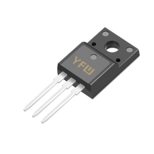
TO-220: The leftmost pin is typically the Gate (G), the middle pin is the Cathode (K), and the rightmost pin is the Anode (A) .
TO-92: The pins are arranged as Cathode (K), Gate (G), and Anode (A) from left to right when viewed with the flat side facing you .
TO-252 (DPAK): The pins follow a similar pattern to TO-220 but in a smaller package.
Bolt-Type SCRs: The metal tab or bolt is the Anode (A), while the two leads are the Gate (G) and Cathode (K) .
YFW’s SCRs: Products like the BTA20-800CW (TO-220A) and MCR100-8 (TO-92) follow these standard pinouts. Always refer to the datasheet for precise details .
A multimeter is a versatile tool for verifying SCR terminals. Here’s a step-by-step guide:
Switch the multimeter to the diode test mode (for digital multimeters) or resistance mode (R×100 or R×1kΩ for analog multimeters) .
Connect the red probe to one terminal and the black probe to another.
Low Resistance Reading: If the reading is low (a few hundred ohms), the red probe is on the Gate (G), and the black probe is on the Cathode (K). This indicates a forward-biased PN junction between G and K .
High Resistance Reading: If the resistance is high, swap the probes. A low reading now confirms the correct G-K identification.
Connect the red probe to the remaining terminal (assumed Anode) and the black probe to the Cathode (K).
Forward Bias: A low resistance reading (0.5–1V in diode mode) confirms the Anode (A) .
Reverse Bias: Reversing the probes should show infinite resistance, indicating proper blocking .
Keep the red probe on the Anode (A) and the black probe on the Cathode (K).
Momentarily connect the Gate (G) to the Anode (A) using a jumper wire. The SCR should trigger, showing low resistance. If it doesn’t, the SCR may be faulty .
Manufacturers like YFW provide detailed datasheets for their SCRs. These documents include:
Pin Configuration Diagrams: Clear illustrations of terminal positions for specific packages (e.g., TO-220, SOT-89) .
Electrical Characteristics: Parameters like trigger current (I<sub>G</sub>) and holding current (I<sub>H</sub>), which are crucial for proper operation.
Application Notes: Guidance on circuit design and terminal identification for different use cases.
For example, YFW’s BT169 (SOT-89) datasheet specifies the Gate (G) as the middle pin, with the Cathode (K) and Anode (A) on either side . Always consult the datasheet for your specific part number.
Faint or Missing Markings: If the package is old or damaged, use a multimeter to verify terminals instead of relying on physical labels.
False Triggering: Ensure the multimeter’s current output is sufficient to trigger the SCR. Some multimeters may not supply enough current for high-power devices .
Open or Shorted Terminals:
Accurate terminal identification is critical in various scenarios:
Motor Control: Properly connecting the Gate (G) ensures precise speed regulation in AC motors.
Power Rectification: Correctly identifying Anode and Cathode enables efficient conversion of AC to DC power.
Light Dimmers: Triggering the SCR at the right phase angle requires accurate Gate (G) connection.
Overvoltage Protection: SCRs in crowbar circuits must have terminals correctly aligned to clamp excessive voltages .
YFW’s SCRs, such as the BT138-800E (TO-220C), are designed for these applications, offering high reliability and fast switching .
Identifying the three terminals of an SCR is a fundamental skill for anyone working with power electronics. By combining physical inspections, multimeter testing, and datasheet references, you can ensure correct installation and optimal performance. YFW’s range of SCRs, including the BTA06-800CW and MCR100-8, adhere to industry standards and provide clear terminal markings for ease of use. Always prioritize safety and consult technical documentation for specific requirements.
For more information on YFW’s SCR products and applications, visit
www.yfwdiode.com