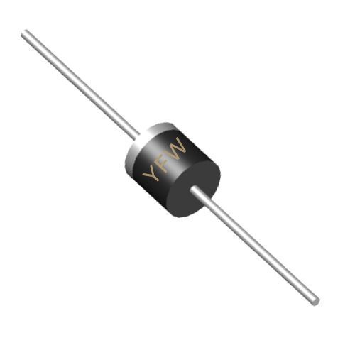
The reverse breakdown voltage is the maximum reverse-biased voltage a diode can withstand before entering a state of avalanche breakdown, where a sudden increase in reverse current occurs . This parameter is critical for applications involving high-voltage environments, such as power supplies and motor control circuits. For example, YFW’s SR560 Schottky diode specifies a reverse voltage (VR) of 60V, ensuring robust performance in low-voltage, high-frequency rectification . Exceeding VBR can lead to irreversible damage, so designers must select diodes with ratings exceeding the maximum expected reverse voltage in their circuits.
The forward voltage drop is the voltage across a diode when it conducts forward current. For silicon diodes, VF typically ranges between 0.6V and 0.7V, while Schottky diodes exhibit lower values (e.g., 0.3–0.5V) due to their metal-semiconductor junctions . YFW’s SS56 Schottky diode, for instance, features a VF of 700mV at 5A, minimizing power dissipation in high-current applications . Lower VF values are desirable for energy-efficient designs, as they reduce heat generation and improve overall system efficiency.
Reverse leakage current refers to the small current that flows through a diode when it is reverse-biased. This parameter is influenced by temperature and manufacturing 工艺. YFW’s SR5100 Schottky diode, rated for 100V reverse voltage, specifies an IR of 50nA, highlighting its low leakage characteristics . High leakage current can cause significant power loss in sensitive circuits, particularly in battery-powered devices. Engineers must prioritize diodes with low IR values for applications requiring minimal standby power.
The maximum forward current is the highest continuous current a diode can carry without exceeding its thermal limits. This parameter is determined by the diode’s junction temperature and package design. YFW’s 20A10 TB rectifier diode, for example, handles up to 20A with a forward voltage of 1V, making it suitable for high-power applications like industrial inverters . Exceeding IF can lead to thermal runaway and device failure, underscoring the importance of derating diodes in high-temperature environments.
Reverse recovery time is the duration required for a diode to switch from the forward-conducting state to the reverse-blocking state. This parameter is critical in high-frequency applications, such as switching power supplies. YFW’s SF36 fast-recovery diode achieves a TRR of 35ns, enabling efficient operation in high-speed rectification . Longer recovery times can cause excessive power loss and electromagnetic interference (EMI), making fast-recovery diodes essential for modern high-frequency designs.
Junction capacitance arises from the depletion region in a diode, affecting its high-frequency performance. This parameter is particularly important in RF and microwave applications. For instance, varactor diodes rely on CJ variation with reverse voltage to tune resonant circuits . YFW’s R4000 general-purpose diode specifies a junction capacitance of 2.8kV, ensuring stable operation in high-voltage, low-capacitance scenarios . Engineers must balance CJ with other parameters to avoid signal distortion in frequency-sensitive circuits.
Thermal resistance quantifies the heat dissipation capability of a diode, measured as the temperature difference between the junction and ambient environment per watt of power dissipated. YFW’s technical documentation emphasizes RθJA in thermal management, as it directly impacts long-term reliability. For example, a diode with a lower RθJA can operate at higher power levels without overheating . Proper heat sinking and thermal design are essential to prevent junction temperature (TJ) from exceeding the maximum rating, typically 150°C for silicon diodes.
Peak inverse voltage is the maximum reverse voltage a diode can withstand during repetitive cycles. It is closely related to VBR but accounts for transient voltage spikes. YFW’s MB6F bridge rectifier, designed for 200–1000V applications, incorporates diodes with high PIV ratings to handle surge voltages in motor control systems . Selecting diodes with PIV exceeding the circuit’s peak reverse voltage ensures robust protection against voltage transients.
The operating junction temperature is the maximum temperature the diode’s PN junction can sustain without degradation. YFW’s diodes are engineered to operate within a TJ range of -55°C to +150°C, ensuring reliability in extreme environments . Exceeding TJ limits can cause parametric shifts, such as increased VF or IR, ultimately reducing device lifespan. Thermal derating curves in datasheets help engineers determine safe operating conditions under varying loads.
Maximum surge current is the peak current a diode can handle for short durations, such as during inrush current events. YFW’s 20A10 TB diode supports a surge current of 200A, making it suitable for applications with high-starting loads . This parameter is critical for protecting diodes in circuits prone to transient currents, such as power supplies and automotive systems.
When selecting diodes, engineers must align parameters with application requirements:
Power Electronics: Prioritize VF, IF, and thermal resistance to minimize losses.
High-Frequency Circuits: Focus on TRR and CJ to maintain signal integrity.
Voltage Regulation: Zener diodes with precise VZ (Zener voltage) are essential.
ESD Protection: Transient voltage suppressors (TVS) with low clamping voltage and high surge capability.
YFW’s product line, including fast-recovery diodes, Schottky barriers, and bridge rectifiers, exemplifies these principles. For instance, the SF36 fast-recovery diode balances TRR (35ns) and VF (1.25V) for efficient switching , while the SR5100 Schottky diode offers low IR (50nA) and high VR (100V) for low-power, high-voltage applications .
Understanding diode parameters is pivotal for designing reliable and efficient electronic systems. YFW Microelectronics empowers engineers with precision-engineered diodes that meet stringent performance standards. By leveraging parameters like VBR, VF, IR, and TRR, designers can optimize circuit performance, ensure thermal stability, and enhance overall system longevity. For detailed specifications and application notes, refer to YFW’s datasheets and technical resources, available at
www.yfwdiode.com.
YFW Microelectronics – Innovating Semiconductor Solutions for a Connected World.
This article adheres to YFW’s technical documentation style, emphasizing clarity, precision, and alignment with industry standards. By integrating real-world examples from YFW’s product line, it positions the brand as a trusted authority in diode technology
