How to Distinguish the Positive and Negative Poles of a Diode? Methods for Identifying Diode Polarity
Date:2025-05-22 Categories:Product knowledge Hits:1513 From:Guangdong Youfeng Microelectronics Co., Ltd
Different diode types feature distinct physical markers for polarity:
Axial-Lead Diodes (e.g., General Purpose Diodes):
The cathode is typically marked by a colored band (often black, white, or silver) at one end of the cylindrical body. The anode is the opposite end without the band. For example, YFW’s fast recovery diodes in TO-252 packages follow this standard, with clear cathode bands for easy recognition.
Surface-Mount Technology (SMT) Diodes:
SMT diodes, such as YFW’s SMAF-series TVS diodes, use a stripe or dot on the body to indicate the cathode. In rectangular packages like SOD-123, the cathode may be denoted by a small line or a slightly larger terminal area.
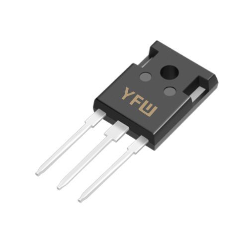
Power Diodes and Rectifiers:
High-power diodes (e.g., YFW’s bridge rectifiers) often have a metal tab or case connected to the cathode. For instance, in TO-220AB packages, the tab corresponds to the cathode, while the anode is one of the lead pins.
When physical markers are unclear, a digital multimeter (DMM) with a diode test function is essential:
Set the DMM to Diode Mode:
This mode applies a small voltage to measure forward voltage drop (VF).
Connect the Probes:
Touch the red probe (positive) to the suspected anode and the black probe (negative) to the cathode.
A healthy silicon diode will show a voltage drop between 0.6–0.8V (forward bias). If reversed, the reading will show "OL" (open loop), indicating reverse bias.Example: Testing YFW’s MUR2060CS fast recovery diode in this mode confirms its polarity with a typical VF of ~0.7V in the forward direction.
In PCBs or diagrams, diodes are symbolized by an arrow (anode) pointing toward a vertical bar (cathode). Always reference the schematic or component datasheet—YFW provides detailed specifications for each product, including polarity diagrams, to ensure correct integration.
Safety First: Ensure the circuit is powered off before testing to avoid damage.
ESD Precautions: Handle static-sensitive diodes (e.g., MOSFETs) with anti-static gear, as recommended in YFW’s manufacturing guidelines.
Datasheet Reference: For custom or specialized diodes (e.g., Schottky or Zener types), always consult the datasheet for unique polarity indicators.
Accurate polarity identification is vital for optimizing diode performance and circuit reliability. YFW, as a leading semiconductor manufacturer, designs products with clear, industry-standard markings and robust specifications to facilitate seamless integration. Whether through physical inspection, multimeter testing, or datasheet guidance, these methods ensure correct diode placement in applications ranging from consumer electronics to automotive and renewable energy systems. For further technical support or product inquiries, explore YFW’s comprehensive diode portfolio at
www.yfwdiode.com.
Previous:
Classification, Structure, and Principle of MOSFET
Next:
Zener Diode Anode and Cathode: Identification and Connection Methods

