Zener Diode Anode and Cathode: Identification and Connection Methods
Date:2025-05-22 Categories:Product knowledge Hits:3217 From:Guangdong Youfeng Microelectronics Co., Ltd
Like all diodes, Zener diodes are polarized components with two terminals: the anode (positive terminal) and the cathode (negative terminal). The key distinction lies in their operational modes:
Forward Bias: When the anode is connected to a higher potential than the cathode (similar to regular diodes), the Zener diode conducts normally, allowing current to flow with a small voltage drop (typically 0.6–0.7V for silicon-based devices).
Reverse Bias: When the cathode is at a higher potential, the diode enters the reverse breakdown region at its specified Zener voltage (Vz). In this state, it maintains a nearly constant voltage across its terminals, making it ideal for voltage regulation.
Misidentifying these terminals can lead to circuit failure, component damage, or even safety hazards.
Most Zener diodes feature physical markings to denote the cathode:
Stripe/ Band: A distinct stripe or band near one end of the diode body always indicates the cathode.
Package-specific Labels: In surface-mount devices (SMDs) like SOD-123 or DO-214AC, the cathode may be marked with a dot or a line on the package.
A digital multimeter (DMM) in diode test mode can accurately determine polarity:
Forward Bias Test: Touch the red probe (positive) to the anode and the black probe (negative) to the cathode. The DMM will display a voltage drop (0.6–1.5V, depending on the Zener voltage).
Reverse Bias Test: Swap the probes (red to cathode, black to anode). In reverse bias, the DMM should show "OL" (overload) unless the applied voltage exceeds Vz, in which case the diode enters breakdown and conducts.
The primary use of Zener diodes is in reverse bias for voltage stabilization. The circuit configuration typically includes:
The Zener diode connected in parallel with the load, with its cathode linked to the positive supply rail and its anode to the negative rail (or ground).
A current-limiting resistor (RS) in series with the diode to prevent excessive current flow beyond the diode’s power rating (Pz = Vz × Iz(max)).
Example Circuit:
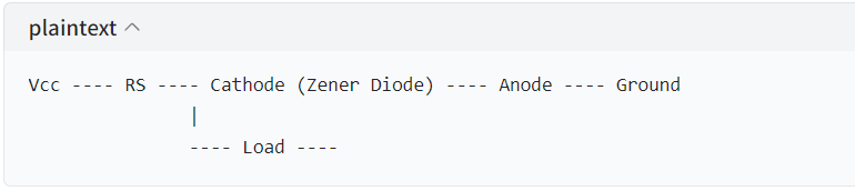
While rare, Zener diodes can also be used in forward bias for standard rectification, though this is not their primary function. In such cases, connect the anode to the positive supply and the cathode to the load, similar to regular diodes.
Power Dissipation: Ensure the Zener diode’s power rating exceeds the expected power dissipation (P = Vz × Iz).
Temperature Effects: Zener voltage may shift with temperature; consult the datasheet for temperature coefficients.
Circuit Protection: Always include a current-limiting resistor in reverse bias configurations to avoid thermal runaway.
Accurate identification of Zener diode terminals and proper circuit connection are fundamental to harnessing their voltage-regulating capabilities. By following the marking guidelines and connection principles outlined here, engineers can design reliable circuits that leverage the unique properties of these components. For high-quality Zener diodes and other semiconductor solutions, explore YFW Microelectronics’ comprehensive product line to meet your design requirements.
Previous:
Classification, Structure, and Principle of MOSFET
Next:
Why Semiconductors?

