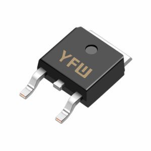
A P-channel MOSFET operates by controlling the flow of holes between the source (S) and drain (D) terminals using a voltage applied to the gate (G). Unlike N-channel MOSFETs, which require a positive gate-source voltage (VGS) to form a conductive channel, PMOS devices rely on a negative VGS to initiate conduction. The fundamental condition for PMOS turn-on is:
VGS = VG - VS < VTH,
where VTH is the threshold voltage (typically a negative value, e.g., -1V to -4V) .
For example, if the source voltage (VS) is 5V and VTH is -1V, the gate voltage (VG) must be below 4V to ensure VGS < VTH and trigger channel formation . This inverse voltage relationship makes PMOS ideal for high-side switching applications, where the source is connected to a positive supply rail.
PMOS devices come in two primary types:
Enhancement Mode: These MOSFETs are normally off (no channel) when VGS = 0V. A sufficiently negative VGS is required to induce a conductive channel.
Depletion Mode: These devices have a pre-formed channel at VGS = 0V. They require a positive VGS to reduce or eliminate conduction.
In most applications, enhancement-mode PMOS is preferred due to its ability to provide full control over switching operations. For instance, in power management circuits, a low gate voltage (e.g., near ground) can turn the PMOS on, allowing current to flow from the source to the drain .
VTH is a critical parameter that determines the minimum VGS required for conduction. For PMOS, VTH is negative (e.g., -1.5V for YFW’s YFW3401), meaning the gate must be sufficiently below the source voltage to activate the device. A lower (more negative) VTH allows for faster switching and reduced power consumption .
To ensure full conduction, VGS must be significantly lower than VTH. For example, if VTH is -2V, VGS should ideally be -5V or lower to minimize the on-resistance (RDS(ON)) and maximize current flow .
The relationship between VGS and VDS determines the operating region of the PMOS:
Linear Region: VGS < VTH and VDS > VGS - VTH. Here, the device acts as a voltage-controlled resistor.
Saturation Region: VGS < VTH and VDS ≤ VGS - VTH. The drain current becomes nearly independent of VDS, making this region suitable for amplifiers .
PMOS excels in high-side switching configurations, where the load is connected to ground, and the MOSFET controls the positive supply rail. For example, in automotive electronics, a PMOS can switch a 12V load by pulling the gate to ground, eliminating the need for a bootstrap circuit required in N-channel designs .
PMOS devices are widely used in voltage regulators and battery protection circuits. Their low RDS(ON) and negative VGS requirement enable efficient power delivery with minimal heat dissipation. YFW’s YFW70P03, for instance, offers a typical RDS(ON) of 20mΩ, making it suitable for high-current applications .
In complementary metal-oxide-semiconductor (CMOS) circuits, PMOS and NMOS transistors work together to form logic gates. The PMOS conducts when the input is low, while the NMOS conducts when the input is high, ensuring low standby power consumption .
Body Effect: When the PMOS substrate (body) is not connected to the source, a reverse bias (VBS) can increase the threshold voltage’s magnitude, requiring a more negative VGS for conduction .
Parasitic Diode: PMOS has a built-in diode from drain to source, which must be considered in circuit designs to prevent reverse current flow .
Voltage Ratings: Ensure the PMOS can withstand the maximum VDS and VGS encountered in the application to avoid breakdown .
P-channel MOSFETs are versatile components that enable efficient voltage control in a wide range of applications. By understanding their conduction conditions—primarily the requirement for a negative VGS relative to the source voltage—engineers can leverage PMOS devices to design robust, low-power circuits. YFW
Diode’s PMOS portfolio, including the YFW3401 and YFW70P03, combines industry-leading performance with reliability, making them ideal for automotive, consumer electronics, and industrial applications.
For technical specifications and design support, visit
YFW Diode to explore our comprehensive range of semiconductor solutions.
