Date:2024-10-09 Categories:Product knowledge Hits:337 From:Guangdong Youfeng Microelectronics Co., Ltd
Testing method for voltage regulator diode
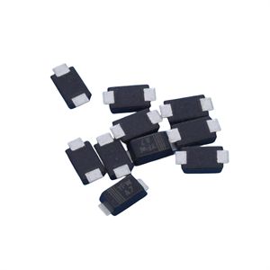
Zener diode SOD-123 package, small in size, can replace glass packaging; Flat pressure film structure; Suitable for automated assembly processes; So, what is a voltage regulator diode?
Zener diode, also known as Zener diode, abbreviated as Zener diode, is a special diode used for voltage regulation (or limiting) and operating in reverse breakdown state. However, rectifier diodes generally cannot operate in the reverse breakdown region, while voltage regulators operate in the reverse breakdown region.
Below is a brief introduction to the detection method of voltage regulator diodes.
1. Determine the electrode
The method for distinguishing the positive and negative electrodes of a voltage regulator diode is basically the same as the method for distinguishing the electrodes of a regular diode. Using the R * 1K range of the multimeter, first connect the red and black probes to both ends of the voltage regulator to measure a resistance value. Then exchange the probes and measure another resistance value. The two measured resistance values should be one large and one small. The smaller resistance value measured is the forward connection method. At this time, the black probe is connected to the positive terminal of the voltage regulator diode, and the red probe is connected to the negative terminal. A good voltage regulator typically has a forward resistance of around 10K Ω and an infinite reverse resistance.
2. Detection of voltage regulation value
1) Simple testing method, which only requires a multimeter. The method is to set the multimeter to Rx10k and accurately zero it. Connect the red probe to the positive terminal of the tested voltage regulator diode and the black probe to the negative terminal of the tested diode. When the pointer reaches a certain position, read the stable data from the DC 10V voltage scale of the multimeter, and then calculate the voltage regulator value using the following formula: the tested voltage regulator value (V)=(10V - read value) x1.5. This method can be used to measure voltage regulators with a voltage regulation value below 15V.
2) External power testing method, connect a 0V~3V stabilized power supply with a 1.5K Ω resistor as shown in the following diagram.
When measuring, first adjust the output voltage of the voltage regulator to 15V, and use a multimeter to directly measure the voltage value at both ends of ZD. The reading is the voltage regulation value of the voltage regulator diode. If the measured value is 15V, it is possible that the diode has not reverse broken down. In this case, the output voltage of the regulated power supply can be increased to 20V or above, and then measured according to the above method.

Previous: Classification, Structure, and Principle of MOSFET
Next: Using voltage inspection method to quickly locate fault points in integrated circuits