Date:2024-09-24 Categories:Product knowledge Hits:417 From: Guangdong Youfeng Microelectronics Co., Ltd(YFW)
What are the internal circuits of the bridge stack? What are the differences in the internal structure of the bridge stack and the polarity of the DC output voltage?
1. Explanation of the internal structure of the bridge stack and the polarity of the DC output voltage:
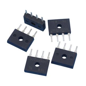
(1) The bridge stack consists of four diodes, which are packaged together to form a whole and lead out four pins.
(2) Bridge stack is usually used to form a bridge rectifier circuit, with its two pins serving as AC voltage input terminals, namely the two pins marked with the symbol "".
(3) When the bridge stack is connected to form a positive DC output voltage circuit, its "-" pin terminal is grounded, and a positive DC voltage is output from the "+" pin terminal.
(4) The bridge stack can also be connected to a negative DC output voltage circuit, where its "+" pin is grounded and a negative DC voltage is output from the "-" pin.
(5) A half bridge stack can form a full wave rectification circuit, and two different types of half bridge stacks can respectively form a full wave rectification circuit that outputs a positive polarity voltage and a full wave rectification circuit that outputs a negative polarity voltage. Two half bridges of different polarities are stacked together to form a bridge rectifier circuit.
2. Explanation of a special half bridge stack:
The two internal diodes are independent of each other, and the electrodes of the two diodes are not connected to each other. This half bridge stack is more flexible in application
and can be easily connected into various forms of application circuits in external circuits. Based on the internal structure and external schematic diagram of this half bridge stack, it is
easy to identify the functions of its various pins.
3、 Explanation of Bridge Pile Identification Methods
(1) Explanation of Bridge Pile Pin Identification Method:
The corresponding positions of each pin on the bridge shell are marked with "", "-", "+", which are consistent with the markings in the circuit diagram, so that each pin can be
distinguished.
(2) Explanation of Bridge Pile Parameter Identification Method:
The shell of the bridge stack is usually marked with QL - × A, where QL represents the bridge stack and × A represents the operating current. For example, QL-3A is marked on a bridge stack, indicating that it is a bridge stack with a working current of 3A.

Previous: Classification, Structure, and Principle of MOSFET
Next: What are the common testing methods for voltage drop of Schottky diodes?