Date:2024-09-24 Categories:Product knowledge Hits:516 From: Guangdong Youfeng Microelectronics Co., Ltd(YFW)
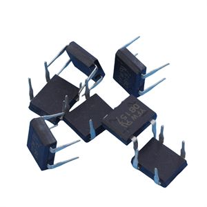
What are the principles behind the design of Schottky diode detection circuits? What are the impacts of the design and analysis of Schottky diode detection circuits? There are many types of bridge rectifiers, including flat, circular, square, bench shaped (divided into direct insertion and surface mount), and GPP and O/J structures. The rectified current ranges from 0.5A to 100A, and the reverse peak voltage ranges from 50V to 1600V.
Half bridge rectifier is a circuit that combines half of two diode bridge rectifiers together. Two half bridges can form a bridge rectifier circuit, and one half bridge can also form a full wave rectifier circuit with a transformer and a center tap.
When choosing a rectifier bridge, consideration should be given to the rectifier circuit and operating voltage.
The rectifier bridge stack is generally used in full wave rectifier circuits, which are divided into full bridge and half bridge.
A full bridge is composed of four rectifier diodes connected in the form of a bridge full wave rectifier circuit and packaged as a whole.
The forward current of the full bridge has various specifications such as 0.5A, 1A, 1.5A, 2A, 2.5A, 3A, 5A, 10A, 20A, 35A, 50A, etc. The withstand voltage (reverse voltage) has various specifications such as 25V, 50V, 100V, 200V, 300V, 400V, 500V, 600V, 800V, 1000V, etc.
The function of bridge rectifier:
1. Convert the alternating current generated by the AC generator into direct current to supply power to electrical equipment and charge the battery;
2. Limit the reverse flow of battery current back to the generator to protect it from being burned out by reverse current.
Bridge rectifier circuit can also be considered as a type of full wave rectifier circuit, with four diodes connected to the transformer winding method. D1 to D4 are four identical rectifier diodes connected in a bridge form, hence the name bridge rectifier circuit. By utilizing the guiding effect of diodes, the secondary output can also be directed towards the load during the negative half cycle. The specific connection is shown in the figure. It can be seen from the figure that during the positive half cycle, the current is guided from top to bottom through RL by D1 and D2, and during the negative half cycle, the current is also guided from top to bottom through RL by D3 and D4, thus achieving full wave rectification. In this structure, if the same DC voltage is output, the secondary winding of the transformer only needs half of the winding compared to full wave rectification. However, if the same current is to be output, the wire diameter of the winding needs to be thickened accordingly. As for pulsation, it is completely the same as the full wave rectification circuit mentioned earlier.
Due to the presence of significant ripple components in the output voltage of rectifier circuits. In order to minimize the pulsation component and preserve the DC component as much as possible to make the output voltage close to the ideal DC, this measure is filtering. Filtering is usually achieved by utilizing the energy storage function of capacitors or inductors.

Previous: Classification, Structure, and Principle of MOSFET
Next: What is the design and analysis principle of Schottky diode detection circuit?