
Date:2026-02-27 Categories:Product knowledge Hits:1209 From:Guangdong Youfeng Microelectronics Co., Ltd
To determine the quality of an optocoupler, one can measure the forward and reverse resistance of its internal diode and transistor in-circuit. More reliable detection methods include the following three:
1. Comparison method: Remove the optocoupler suspected of having a problem, use a multimeter to measure the forward and reverse resistance values of its internal diode and transistor, and compare them with the measured values of the corresponding pins of a good optocoupler. If the resistance values differ significantly, it indicates that the optocoupler is damaged.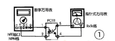
2. Digital multimeter detection method Taking the detection of PC111 optocoupler as an example, the detection circuit is shown in Figure 1. During the detection, insert the + terminal {1} pin and - terminal {2} pin of the optocoupler's internal diode into the c and e jacks of the digital multimeter's Hfe, and set the digital multimeter to the NPN mode. Then, connect the c terminal {5} pin of the optocoupler's internal phototransistor to the black probe of the analog multimeter, and connect the e terminal {4} pin to the red probe, with the analog multimeter set to the R×1k range. In this way, the condition of the optocoupler can be judged by the deflection angle of the analog multimeter's pointer, which is actually the change in photocurrent. The larger the pointer deflection angle to the right, the higher the optocoupler's photoelectric conversion efficiency, that is, the higher the transmission ratio; conversely, it indicates a lower efficiency. If the pointer does not move, it means that the optocoupler has been damaged.
3. Photoelectric Effect Judgment Method: Still taking the detection of the PC111 optocoupler as an example, the detection circuit is shown in Figure 2. Place the multimeter in the R×1k resistance range, with the two probes connected to the output terminals {4} and {5} of the optocoupler respectively. Then, connect a 1.5V battery in series with a 50~100Ω resistor, with the positive terminal of the battery connected to the {1} pin of the PC111 and the negative terminal touching the {2} pin, or with the positive terminal touching the {1} pin and the negative terminal connected to the {2} pin. At this time, observe the pointer deflection of the multimeter connected to the output terminal. If the pointer swings, it indicates that the optocoupler is good. If it does not swing, it indicates that the optocoupler is damaged. The larger the deflection angle of the multimeter pointer, the higher the photoelectric conversion sensitivity.
Previous: Classification, Structure, and Principle of MOSFET
