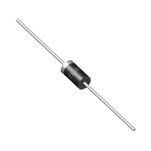
A thyristor consists of alternating P-type and N-type semiconductors (PNPN structure), forming three PN junctions: J1, J2, and J3. In the off-state, J1 and J3 are forward-biased, while J2 is reverse-biased, blocking current flow from the anode to the cathode. For the thyristor to conduct, a positive voltage must be applied to the gate relative to the cathode, injecting minority carriers into the J2 junction. This triggers a regenerative effect: the forward-biased junctions start conducting, and the device switches to the on-state. Once conducting, the gate loses control, and the thyristor remains on until the anode current drops below a critical value (holding current) or the voltage reverses.
The transition from off to on-state is rapid, making thyristors ideal for switching high-power circuits. To turn them off, the anode current must be reduced below the holding current, typically by interrupting the power supply or using forced commutation techniques. This unidirectional conductivity and switching capability make thyristors suitable for applications like motor control, rectifiers, and power regulators.
Forward Breakover Voltage (VBO): The minimum anode-cathode voltage that triggers conduction without gate current. Exceeding VBO can cause uncontrolled switching, damaging the device.
Peak Working Voltage (VDRM/VRRM): The maximum repetitive voltage the thyristor can block in the forward (VDRM) or reverse (VRRM) direction without breakdown. Ratings must exceed the circuit’s transient voltages.
Average On-State Current (IT(AV)): The maximum average current the thyristor can handle in the conducting state, determined by junction temperature and thermal management. Exceeding this value leads to overheating and failure.
Holding Current (IH): The minimum anode current required to maintain conduction. If the current drops below IH, the thyristor turns off.
Gate Trigger Current (IGT) and Voltage (VGT): The minimum current and voltage needed at the gate to initiate conduction. Low IGT/VGT values improve sensitivity but may increase susceptibility to noise.
dv/dt and di/dt Ratings: dv/dt is the maximum rate of voltage rise the device can withstand without false triggering, while di/dt limits the rate of current rise to prevent junction hotspots.
Turn-On and Turn-Off Time: Turn-on time is the delay from gate signal application to full conduction, and turn-off time is the recovery period after current interruption. These parameters affect switching efficiency and power losses.
Thyristors are indispensable in modern power electronics due to their ability to control high voltages and currents with precise triggering. Their working principle relies on the PNPN structure’s regenerative switching, while key parameters like voltage ratings, current capabilities, and switching speeds dictate their suitability for specific applications. Engineers must carefully match these parameters to circuit requirements, ensuring reliable operation and optimal performance. By understanding how thyristors conduct and the factors influencing their behavior, designers can harness their potential in diverse systems, from industrial machinery to renewable energy converters
