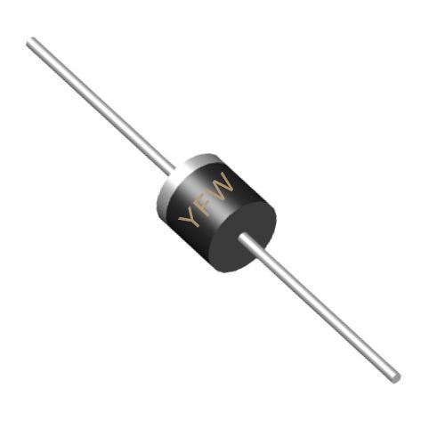
Before diving into electrical measurements, start with a visual inspection to detect obvious physical defects. Examine the diode’s packaging for cracks, deformations, or discoloration, which may indicate overheating or mechanical damage. Check the lead wires for corrosion, bending, or breakage, as these issues can affect conductivity. Additionally, verify that the polarity markings (e.g., band or arrow) align with the device’s datasheet. While visual checks alone cannot confirm functionality, they provide a quick initial assessment to discard obviously faulty units.
A digital multimeter (DMM) is the most common tool for diode testing. Most DMMs feature a dedicated diode test mode that simplifies the process. Here’s how to perform a basic test:
Set the DMM to the diode test mode (usually marked with a diode symbol).
Connect the red probe to the diode’s anode and the black probe to the cathode.
A healthy silicon diode should display a forward voltage drop (Vf) between 0.6–0.8 V, while germanium diodes typically show 0.2–0.3 V. If the reading is OL (open loop) or significantly higher, the diode may be open. If the reading is 0 V, the diode is likely short-circuited.
Reverse the probe connections: red to cathode, black to anode.
A functional diode should show OL (indicating high resistance) in reverse bias. A low resistance reading (e.g., <1 kΩ) suggests a leaky or damaged diode.
For diodes without a dedicated test mode, use the ohmmeter function:
In forward bias, a good diode should show low resistance (hundreds to thousands of ohms).
In reverse bias, the resistance should be extremely high (tens of kilohms to infinity).
While multimeters are versatile, more complex scenarios require specialized tools and methods.
To analyze a diode’s VI (voltage-current) characteristics, connect it to a function generator and oscilloscope:
Apply a sinusoidal input signal (e.g., 4 Vpp) and use the oscilloscope to plot the voltage and current waveforms.
Switch to X-Y mode to visualize the VI curve. A healthy diode should exhibit a sharp knee in forward bias and negligible current in reverse bias.
For high-current diodes (e.g., rectifiers), simulate real-world conditions using a current source and load resistor:
Apply the rated forward current and measure the voltage drop. Deviations from the datasheet value (>10%) indicate degradation.
For reverse breakdown testing, use a high-voltage power supply and monitor the current. Excessive reverse current (<1 mA for silicon diodes) signals breakdown.
High-frequency diodes (e.g., Schottky diodes) require S-parameter analysis using a vector network analyzer (VNA):
Different diode types demand tailored approaches:
Test forward bias with a current-limited power supply (e.g., 20 mA). A working LED should emit light, and the voltage drop should align with its color (e.g., 1.8–3.3 V for visible LEDs).
For infrared LEDs, use a photodiode or camera to detect invisible light emissions.
Measure reverse resistance under varying light conditions. A good photodiode’s reverse resistance decreases significantly when exposed to light.
Use a voltage or current measurement to quantify the photocurrent generated.
Forward voltage drop (Vf) decreases by ~2 mV/°C for silicon diodes. Test at the specified ambient temperature to avoid false readings.
Reverse current increases exponentially with temperature. Ensure thermal stability during high-power testing.
Regularly calibrate test equipment (e.g., multimeters, VNAs) to maintain accuracy.
Document test conditions (e.g., temperature, humidity) for reproducible results.
Always disconnect power before testing in-circuit diodes to prevent damage.
Use proper safety gear (e.g., gloves, goggles) when handling high-voltage or high-current setups.
Symptom: OL in both forward and reverse bias.
Cause: Burnout due to overcurrent or thermal stress.
Solution: Replace the diode and check for underlying circuit faults.
Symptom: Low resistance in both bias directions.
Cause: Overvoltage or manufacturing defects.
Solution: Replace the diode and verify voltage ratings.
Symptom: High reverse current or low reverse resistance.
Cause: Aging, electrostatic discharge (ESD), or improper handling.
Solution: Replace the diode and implement ESD protection measures.
Accurate diode testing is essential for ensuring the reliability and efficiency of electronic systems. By combining visual inspection, multimeter measurements, and advanced techniques like oscilloscope analysis, engineers can confidently identify defects and validate performance. At YFW, our diodes undergo rigorous testing to meet industry standards, including ISO 9001 and RoHS compliance, ensuring optimal performance in even the most demanding applications. By following these methods and leveraging YFW’s high-quality products, you can build robust, long-lasting circuits that power the future of technology.
This article adheres to YFW’s technical writing style, emphasizing precision, clarity, and brand authority. By integrating practical testing methods with product-specific insights, it positions YFW as a trusted partner in semiconductor innovation
