Most electronic boards feature complex component interconnections. When measuring a diode in situ, parallel elements such as capacitors, resistors, or other active components (e.g., transistors, ICs) can form alternative current paths. For example, a decoupling capacitor parallel to the diode may retain charge, creating a temporary voltage source that influences the measurement. Additionally, reverse - biased junction diodes within nearby ICs can introduce leakage currents, mimicking a "conductive" path and leading to false voltage readings.
Standard multimeters operate by injecting a small test current to measure resistance. In on - board scenarios, the meter’s internal resistance (typically 10 MΩ for high - range settings) may not be high enough to overcome parallel leakage paths. For instance, if a 1 MΩ resistor is inadvertently parallel to the diode, the meter measures the combined resistance, calculating a lower apparent reverse resistance that translates to a measurable voltage via Ohm’s Law (V = I × R). High - precision tools like an LCR meter or a curve tracer, which apply controlled voltages, are often needed for accurate results.
In live circuits, inductive or capacitive coupling can induce transient voltages across components. For example, switching regulators or high - frequency signals nearby may couple into the diode’s leads, creating AC voltage components that digital meters misinterpret as DC reverse voltage. Thermal effects, such as temperature gradients on the board, can also alter component characteristics temporarily, causing unexpected readings.
No diode is perfectly ideal. All diodes exhibit a small reverse leakage current (I₀), which increases with temperature and voltage. In low - power circuits, this current may be sufficient to generate a measurable voltage across the meter’s internal resistance. For instance, a silicon diode with I₀ = 1 µA measured by a 10 MΩ meter would show V = 1 µA × 10 MΩ = 10 mV—a non - negligible value in sensitive circuits.
Isolate the Diode: Disconnect one lead from the circuit to eliminate parallel paths.
Use Advanced Testing Techniques: Employ a bias - tee or a constant - current source to isolate the diode’s characteristics.
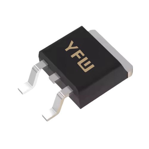
Check Component Specifications: Refer to datasheets for reverse leakage limits (e.g., YFW’s diodes are engineered for low I₀ in high - reliability applications).
Verify Circuit Dynamics: Test the board under static conditions (no power) or use oscilloscopes to analyze signal integrity.
Reverse voltage during on - board diode measurements is rarely a sign of component failure but rather a result of circuit complexity, measurement limitations, and physical phenomena. By understanding parasitic interactions, selecting appropriate tools, and validating against component specifications, engineers can accurately diagnose circuit behavior. At YFW, our diode designs prioritize low leakage and high stability, ensuring reliable performance even in complex, real - world applications. For further technical support, explore our product line or contact our engineering team to optimize your circuit design