How to Distinguish Positive and Negative Poles of Diodes
Date:2025-05-16 Categories:Product knowledge Hits:2735 From:Guangdong Youfeng Microelectronics Co., Ltd
Most diodes feature obvious physical indicators to denote their polarity:
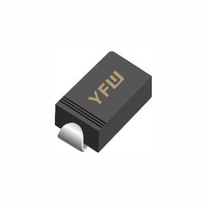
Stripes or Bands: The cathode is typically marked with a colored stripe (often black, white, or silver) near one end of the diode body. For example, standard rectifier diodes like YFW’s high-voltage diodes usually have a single stripe at the cathode side.
Case Shapes: Some diodes, such as power diodes in TO-220 or TO-252 packages, use structural cues. The cathode may be connected to the metal tab or case, while the anode is the lead opposite the tab.
LEDs (Light-Emitting Diodes): In LEDs, the cathode is often the shorter lead, and the internal metal plate near the cathode is larger than the anode’s.
A digital multimeter is a reliable tool for testing diode polarity:
Set the Meter: Switch the multimeter to the diode test mode (usually denoted by a diode symbol) or the ohmmeter function.
Test Connections: Touch the multimeter’s red probe (positive) to the diode’s anode and the black probe (negative) to the cathode. In this direction, the diode should show a low resistance reading (forward bias). If reversed, the reading should be “OL” (open loop) or very high (reverse bias).
Note: For Schottky diodes or fast-recovery diodes (e.g., YFW’s MUR2060CS), the forward voltage drop may be lower (0.3–0.5V) compared to standard silicon diodes (0.6–0.7V), but the polarity testing method remains the same.
Manufacturer datasheets provide detailed polarity information for each diode model. For instance, YFW’s product pages (available at
https://www.yfwdiode.com/) include pin diagrams and package drawings clearly labeling anode and cathode terminals. Always consult the datasheet for specialized diodes like TVS diodes (e.g., SMAF10CA) or MOSFETs, where polarity may vary with package types.
In pre-assembled circuits, the PCB silkscreen often marks diode polarity with a “+” for the anode or a “C” (cathode) near the component footprint. If unsure, trace the connections to the power source or ground, as the cathode typically connects to the negative side of the power supply in forward-biased configurations.
Safety First: Ensure the circuit is powered off before testing diodes to avoid damage or inaccurate readings.
Quality Assurance: Using high-reliability diodes from trusted manufacturers like YFW minimizes polarity confusion, as their products adhere to strict industry standards.
Specialized Diodes: For bidirectional components (e.g., some protection diodes), polarity may not apply, so always verify the component type first.
By mastering these methods, engineers and hobbyists can confidently install diodes, optimizing circuit performance and reliability. For more technical resources or YFW’s comprehensive diode solutions, visit
https://www.yfwdiode.com/ to explore our product catalog and technical support.
Previous:
Classification, Structure, and Principle of MOSFET
Next:
The Role of Connecting the Negative Terminal to the Diode's Cathode

