Theoretical Advantages:
Parallel configurations are often employed to enhance surge current handling capabilities. By distributing the transient energy across multiple devices, the total peak pulse current (IPP) and power (PPM) can be effectively increased. For example, three TVS diodes rated at 71.7 A each can collectively handle 150 A when paralleled, as demonstrated in industry tests . This approach is particularly beneficial in high-power applications, such as automotive systems or industrial equipment, where single devices may struggle to absorb extreme surges.
Key Challenges:
Parameter Mismatch: Even minor variations in breakdown voltage (VBR), clamping voltage (VC), or dynamic impedance can cause uneven current sharing. The device with the lowest VBR will conduct first, potentially leading to premature failure .
Response Time Synchronization: TVS diodes in parallel must activate simultaneously to ensure balanced energy dissipation. Differences in turn-on speed can result in overloading of slower-responding devices .
Capacitance Impact: Parallel connections increase the effective capacitance (CJ), which may degrade high-frequency signal integrity. This is critical for data lines or RF circuits .
Best Practices:
Select Matched Devices: Use identical part numbers from the same production batch to minimize parameter variations.
Pre-Test Voltage Matching: Verify VBR and VC consistency using standardized waveforms (e.g., 8/20 μs) before deployment .
Add Current-Limiting Resistors: Series resistors can help balance current distribution in critical applications .
Theoretical Advantages:
Series connections allow engineers to achieve higher reverse standoff voltages (VRWM) or breakdown voltages (VBR) than single devices. For instance, two TVS diodes with VRWM = 18 V can be series connection to create a 36 V protection solution . This is valuable for systems operating at voltages exceeding the ratings of standard TVS diodes.
Key Challenges:
Voltage Division : Leakage current (IR) differences can cause unequal voltage distribution, stressing individual devices. Strict IR matching is essential to avoid premature breakdown .
Increased Clamping Voltage: Series configurations raise the total clamping voltage (VC), which may exceed the tolerance of downstream components. Careful calculation of VC is necessary .
Complex Layout: Series connections require additional board space and may introduce parasitic inductance, affecting transient response .
Best Practices:
Match Leakage Current: Select devices with tightly controlled IR to ensure uniform voltage sharing.
Calculate Total VC: Use the formula 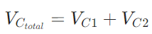 to avoid exceeding component limits.
Optimize Layout: Minimize trace inductance to maintain fast response times.
At YFW, we design TVS diodes with stringent parameter control to enable reliable parallel and series operation. Our products, such as the SMAJ and SMBJ series, undergo rigorous testing to ensure:
Tight VBR and VC Tolerances: ±5% or ±10% accuracy for critical applications.
Low Capacitance Options: Ideal for high-speed data lines (e.g., USB, HDMI).
High-Surge Capability: Up to 30 kW peak pulse power for automotive and industrial environments.
For custom solutions, our engineering team provides support in selecting the optimal configuration and validating performance through surge testing (e.g., ISO 7637-2 for automotive applications) .
TVS diodes can indeed be used in parallel or series, but success hinges on meticulous design and component selection. Parallel configurations enhance surge handling but demand parameter matching, while series setups enable higher voltage protection at the cost of increased clamping voltage. YFW’s advanced TVS diode portfolio, combined with our technical expertise, ensures reliable and efficient protection for diverse applications.
For more information on YFW’s TVS diode solutions, visit
www.yfwdiode.com or contact our engineering team for tailored recommendations.