Date:2025-03-03 Categories:Product knowledge Hits:615 From:Guangdong Youfeng Microelectronics Co., Ltd
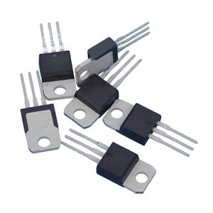
How to measure the quality of bidirectional thyristors
A multimeter can be used to determine the quality of a bidirectional thyristor, but specific parameters cannot be measured.
The method of measuring with a multimeter is as follows:
1. Determination of T2 pole: Use a multimeter R * 1 or R * 100 to measure the reverse resistance of each pin separately. If the forward and reverse resistance of both pins is very small (about 100 ohms), it is the T1 and G poles, and the remaining pin is the T2 pole.
2. The distinction between T1 and G poles: Assuming that either pole is T1 and the other pole is G, set the multimeter to R * 1 level, and use two probes (regardless of positive or negative poles) to contact the determined T2 pole and the assumed T1 pole respectively, and simultaneously contact the probe that contacts T1 with the assumed G pole. While ensuring that the assumed T1 pole is not disconnected, disconnect the assumed G pole, and the multimeter will still display a conductive state.
3. Swap the probes and measure using the same method. If the multimeter still displays the same result, then the assumed T1 and G poles are correct. If the G pole of the hypothesis is disconnected while ensuring that the T1 pole is not disconnected, and the multimeter displays the disconnected state, it indicates that the T1 and G poles of the hypothesis are opposite. If a new hypothesis is used for measurement, the result will definitely be correct.
If the above results cannot be measured, it indicates that the bidirectional thyristor is faulty. Although this method cannot measure specific parameters, it is still feasible to determine whether it is usable.
Conditions for the use of bidirectional thyristors
(1) Under external voltage, it is allowed to exceed the forward transition voltage, otherwise the control electrode will not function.
(2) The average on state current of a thyristor is generally taken as 1.5 to 2 times the maximum current from a safety perspective.
(3) To ensure reliable triggering of the control electrode, the triggering current applied to the control electrode is generally greater than its rated value. In addition, protective measures must be taken. The general protection measure for overcurrent is to connect a fast fuse in series in the circuit, with a rated current of about 1.5 times the average current of the thyristor. Its connection position can be on the AC side or DC side, and the rated current should be higher when it is on the AC side.
The former is generally used, and overvoltage protection often occurs in circuits with inductance, or in surge voltages caused by interference on the AC side or overvoltage generated by transient processes on the AC side. Due to the high peak and short duration of overvoltage, resistance and capacitance absorption circuits are often used to suppress it.
Previous: Classification, Structure, and Principle of MOSFET
Next: The difference between bidirectional thyristor and unidirectional thyristor