Date:2024-10-16 Categories:Product knowledge Hits:638 From:Guangdong Youfeng Microelectronics Co., Ltd
Schottky diodes are very common in power supply design, high-frequency circuits, and other applications that require fast rectification due to their low forward voltage drop and fast switching characteristics. Correctly identifying the positive and negative poles of Schottky diodes is crucial to ensure the correct connection and function of circuits.
1. Tag recognition
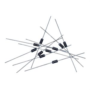
Schottky diodes typically have clear markings on their casing to distinguish between the anode (Anode) and cathode (Cathode). These markings may be letters, symbols, or color bands. For example, many Schottky diodes have one or more circular stripes (usually silver or black) at the cathode terminal, while the anode terminal does not have such markings.
2. Data manual query
For any electronic component, querying its data manual is the best way to obtain accurate information. The data manual for Schottky diodes typically provides packaging details, including markings for identifying the anode and cathode. Sometimes, they also provide packaging diagrams and pin configuration diagrams, which can clearly display which pin is the anode and which is the cathode.
3. Appearance inspection
In the absence of obvious markings, the positive and negative poles of a diode can be inferred by examining its shape. For example, in some types of Schottky diodes, the anode terminal may be slightly wider than the cathode terminal. But this method is not always accurate, especially in small SMD (Surface Mount Device) components.
4. Use a multimeter
A multimeter is a practical tool for determining the positive and negative terminals of Schottky diodes. Set the multimeter to diode test mode, contact one pin of the diode with a red probe and the other pin with a black probe. If the display shows a lower voltage value (usually between 0.2V and 0.4V), the red probe is in contact with the anode and the black probe is in contact with the cathode. If OL or no reading is displayed, it indicates that the probe is in the opposite direction of contact.
5. Circuit position determination
Given a known circuit, the positive and negative terminals of a Schottky diode can be inferred based on the circuit design. For example, in rectifier circuits, the anode of a Schottky diode is usually connected to the AC input terminal, while the cathode is connected to the DC output terminal.
6. Relying on experience
With the accumulation of experience, the positive and negative terminals of Schottky diodes can be quickly determined by observing their packaging type and other physical characteristics. Although this method may not be suitable for beginners, it is a fast and effective approach for experienced engineers.
Correctly determining the positive and negative terminals of Schottky diodes is crucial for the proper assembly and functionality of circuits. This can be achieved through various methods such as tag recognition, data manual query, visual inspection, use of multimeter, circuit position determination, and relying on experience. In practical applications, it is recommended to combine the above methods to ensure accurate identification of the positive and negative terminals of Schottky diodes.

Previous: Classification, Structure, and Principle of MOSFET
Next: Using voltage inspection method to quickly locate fault points in integrated circuits